


Making of Jedda / Robert Pashayan

Hello, my name is Robert Pashayan, currently working partially as Technical Director and Character Artist in the character creation departement (it includes modeling/texturing/shading & grooming) at Unit-Image. I also supervised within the same department on the following projects: “God of war 4 “(commercial), “Beyond Good and Evil 2”(both trailers) and “Beyond the Aquila Rift”(Netflix Short).
As a Technical Director I have to ensure the technical comfort of the Artists within the department and create tools / workflows to boost their performances.
It involves a lot of coding in Python, Maxscript, OSL for tools but also structuring the workflow within the global pipeline, as you can imagine I’m lazier than most of the Artists as I prefer to automate a lot of tasks via the magic of coding.
Project Intro and Conception
After finishing the game Mad Max(2015) I was very inspired by the Universe, without forgetting the movie which left me speechless, especially the performance of Charlize Theron as Furiosa.
My goal was to make a badass female character who’s a mercenary within a cruel primal/post-apocalyptic world.
When making a character I think it is really important to imagine an environment where the character grew, as it helps to define her psychological profile and the physical build.
The concept for Jedda evolved gradually as I wanted to make something stylized it was more cartoonish in the beginning, but after many iterations I made her more realistic.

Building the character
ACES, Arnold, Max to Houdini
I’d like to start this chapter by mentioning ACES(Academy Color Encoding System), it’s the new standardized color management system which makes the visualization of the numerical data more consistent with what our eyes are used to seeing. To learn more, I recommend you to read the free online book of Chris Brejon : https://chrisbrejon.com/
I started to build the character in 3ds max using Arnold for the first time, but as I had issues with rendering hair with Arnold in 3ds max it was a show stopper and I had to preview what the images really look like in Nuke, as the Render Buffer of Arnold in Max doesn’t have OCIO. So I have decided to get out of my comfort zone and test everything in this amazing software which is gaining more and more popularity called Houdini.
As I’m very new too Houdini my workflow might be very primitive for the senior users of Houdini.
Refinement of the volumes, adjustments of the elements
After rebuilding the shaders in Houdini as I already started them in 3ds max, I switch to modeling to ensure that the anatomy is correct, I must emphasize the importance of mimicking natural forces and behaviors like gravity, elasticity, volume conservation, while placing objects on each other, by respecting things as such we get the natural look and the lack of which very often makes digital images subconsciously appear as non-realistic.
 ________________________________

Zbrush Workflow
Since I discovered XYZ maps, I tried a couple of workflows, one of the first approaches were the following :
Project them in zbrush after painting them in mari, and exporting one displacement map including all.
I find this method very costly and slow as to support the same amount of detail I have to subdivide much more, which ends in having many separate subtools to allow zbrush function .
My latest workflow in zbrush consists of:
-Projecting the maps on a separate layer to have the information, reinforcing the details I need on another layer, deactivating the layer where XYZ is imported and exporting my Displacement map.
-The XYZ displacement and Zbrush displacement are added to each other in Houdini.
Final look of the subdivided mesh in Zbrush.
6 subdivisions / 25.000.000 polygons for the whole body

Structure of layers
- XYZ_imprint contains one of XYZ channels in general I use the mid one added with low frequencies
- XYZ_compensation is the layer where I accentuate things that are not strong enough on XYZ maps
- Additional_Details are everything else unrelated with XYZ maps

Painting Maps
As I mentioned before I prefer to stay as much possible procedural, in reality almost everything is possible to achieve procedurally it’s just a matter of time spent on the process, but when I need to bring variation and authenticity to something I go artisanal and handpaint maps.
- The Color and Displacement are XYZ maps on the head, the body has also XYZ displacement but the Color on the body is hand painted.
- The roughness map is defining zones by R,G,B channels of the map, they are in additively painted, which allows me to split them later in Houdini and assign the values I like to them.
- Dirt masks are similar to Roughness they are additive and each chanel represent one matter, Red - Oil, Green - Rust, Blue - Dust.
- Similar Dirt Map is generated in Substance Painter for the props.

I’m starting my projection of XYZ maps in Nuke by wrapping and deforming the texture to fit to the UVs, Nuke’s procedural system allows us to easily change the input from color to displacement and apply the same transformations, so the connection between them is preserved. For this procedure I have UV channel where the whole head is on a single UDIM. Once I have fairly decent result I transfer the maps on a second channel where the UVs are more optimized and this channel consists of 6 UDIMs for the head, and at this point the refinement phase starts in Mari.
1UDIM unwrapping
6 UDIM unwrapping
An important point about the UVs and the texture sizes.
6 UDIM 4K maps will give you the resolution equal to 1 UDIM 16K map, this optimisation is essentially based on better flattened parts as their are more cuts, as we are not trying to have one connected uv island there’s less stretching and squeezing. You can also see on 1 UDIM version the most important parts of the face are squeezed in the center where the non visible back of the head is stretched and taking a lot of territory, this basically means more density on the back and less on the face..
But most importantly a 16K map is very heavy to handle by softwares and it weighs more than 1GB, where 4k will be around ~36Mb(36x6=216MB) a lot lighter, the tiled TX conversion will make this less noticeable for a smart renderer but it’ll still be painful for Nuke and Mari.
P.S I always use 16bit floating exr files for textures, besides few textures downloaded from the web.
ACES Painting workflow in MARI
If you are familiar with MARI a good GPU is needed if you’re on GTX series I’d recommend x80 models, they seems to be the most adapted for Mari.
Before starting painting in MARI I must always check couple of parameters:
- The settings of the Channel : 4k resolution 16bit depth for 6 UDIMS on the head was enough for me.
- The settings of the paint buffer, I’d go for 4k to not have any data loss
Once is all set I’ll paint in small patches, I’ll project a portion in the parts which have issues, I bake it on the Channel’s Layer(the baking option doesn’t clean the paint buffer), then I switch the texture into the buffer from color to displacement or vise versa and fill the same region with the map and then bake this into corresponding Channel’s layer. This process will become much easier if one day MARI would have multi channeled painting system.
P.S. it's always good to have couple of Blendshapes added to your mesh versions, like closed eyes and open mouth to have access to these parts of the mesh, which are otherwise hard to reach.
The settings of the XYZ Maps in MARI’s Image Manager.

The Color map should be set as sRGB texture to have the correct visualisation

The displacement map is a data map so we can just check the RAW data toggle and no colorspace conversion will be applied.
The Settings of the Color Channel and the Layer where XYZ is Painted

The Settings of Displacement Paint Node and Channel


- Select the Color Paint Node, Drag and Drop XYZ Color map to your MARI viewport
- Paint a region
- Set the Bake Behavior to Manual in Painting Panel
- Bake your painting
- Double click on the Displacement Painting Node
- Drag and Drop the XYZ Displacement map to your Mari Viewport
- As the Old Painting wasn’t erased after baking you can see the region and carefully fill it.
Final Result of painted maps

Substance RGB Dirt map generated(mostly procedural) for the props.

Shading inside Houdini with Arnold
Setting the Displacement:
As I mentioned before, Zbrush Displacement is added to XYZ directly in Houdini, this way I can manually adjust every channel’s intensity to obtain the best result within the render with fully setted shaders.

Skin Shader’s SSS Settings

The scale will depend from your Software and it’s Unit system, so this value might be different for other softwares.
As you can see I don’t use variation in Specular amount but rather in IOR to stay more physically accurate.
Dirt RGB Masks and their connections:
Initially I made a Layered Shader and used every painted Dirt Map channel to layer above the Skin Material,so there was a separate Oila, Rust and Dust Materials, but this was extremely coasty at rendering, so I quickly switched to one shader solution, which is completely doable as Arnold has an uber-shader but problematic at the level of organisation.
So to achieve this I used Layered Float and Layered RGB nodes to mix the values for each material input using the Dirt Map.

To sort the mess I used Houdini’s powerful Subnetwork system to organise the nodes whenever one of the shader’s channels is becoming complicated.
Bellow you can see what’s inside a “COL” Subnetwork

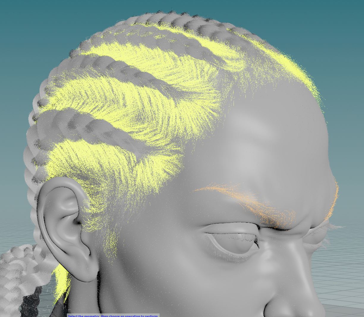
Procedural Grooming in Houdini
The entire grooming is done in Houdini, it was a bit of a challenge for an Ornatrix user but after getting used to the new workflow I discovered a very powerful grooming features.
Houdini’s procedural workflow is very unified, this allows us to use things which can be involved for example in poly modeling,FX etc also for grooming, and the possibilities become limitless.
For the hair braids I had a lot of fun developing a tool in Houdini which generates braids out of a single line, as you can see in the picture below.
It made super easy the grooming process, so basically I had to trace the line for each braid and the hair was generated on them.
Originally I tried to used them as guides and interpolate the hair from it but it wasn’t working well, so I optimized my tool to generate the full amount of hair directly by it, and Houdini was amazing in managing all this heavy data.

After Setting the braids I created other hair systems which insert themselves into the braids.
Normally this should be a part of a unified system to be completely realistic, but it was very hard to handle.
Useful tips
I want to share the few important thing I learned during my 8+ years of experience at work. In general when having issues try to always go to the source of your problem and don’t solve issues with patches and hotfixes.
One example illustrated below is the red spot in the ears, which is caused by the rim light, I had students and colleagues and myself included in the past using masks of SSS radius, intensity or some other hack to fix this kind of issues, while the root of the problem is in the modeling of the volumes.If the radius of your SSS shader is well set and the shapes of your ears are good in most of the cases it’s all you need to have a decent rendering result.
Second example in the image is the strong roughness, which is driven by a map, so I can adjust the value of roughness in Houdini, or go back to Mari and fix the map. The latter is the right solution.
Exemple 1

Final Result


| We would like to thank Robert for his helpful contribution. If you're also interested to be featured here on a topic that might interest the community, feel free to contact us! |