


Hello I’m Ryan Reid and I am a Freelance 3D Character Artist that provides quality work for games and marketing. My knowledge of expertise involves texturing, shading, lighting, rendering, compositing, grading, organic and hard surface modeling, blendshapes, and some facial rigging. I am technically artistic while always striving to make complicated things simple! For this is the reason why I turn to Texturingxyz for the finest skin textures on the planet!

It's been a long journey for me as a 3D artist starting at 8 years old to present at 25 years old. During my journey being a self-taught artist I was heavily inspired by Mike Nash. His vision as a hard surface artist and concepting skills inspired me to learn both organic and hard surfacing. I believe future Artists should and will evolve and be willing to push to specialize in many different areas of the 3d process.
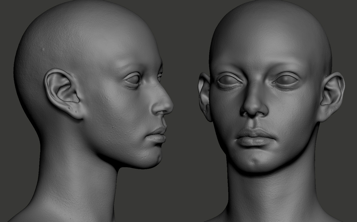
Part 1- Sculpting Unique Faces
When I started this project, I wanted to make sure my face was unique and interesting to look at. I normally would research and find references online using places like Pinterest as my main site for unique references that I found to be appealing.

After getting my reference in order, I start to find my own forms of what I wanted in a face. After sculpting for a while I start to concept my own features and what I find to be appealing in my eyes. Adding features like a chin dimple and a longer neck allows my visual library to process something different in a character. It becomes different from the norm in what we may typically see in a 3D character.

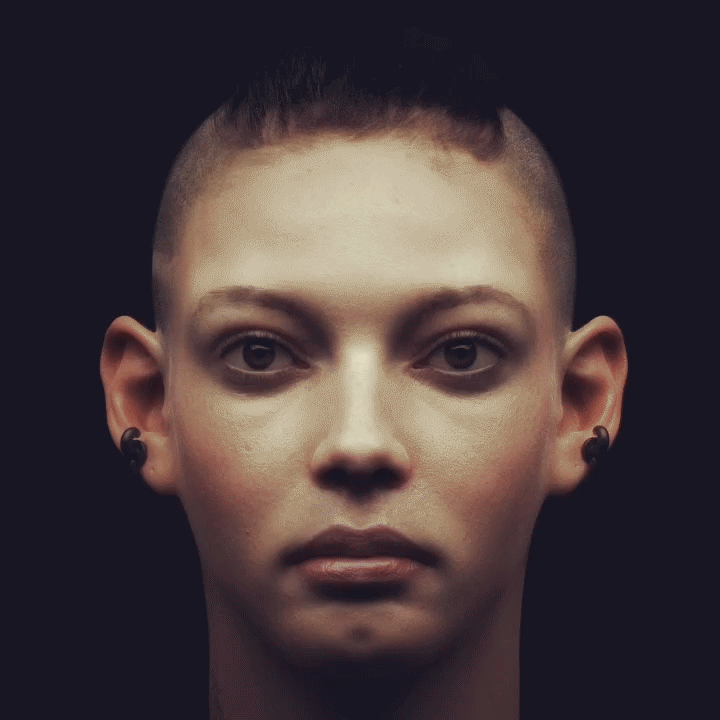
Next, I used the Texturingxyz Micro Skin Face #01 for the surface appliance. I use the surface noise “Noise Maker” to apply various intensities and sizes to different skin regions of the face as shown in the gif. I would normally apply this to a layer for more control for surface blending between each appliance.

After layering XYZ and hand sculpting details by hand I ended up with a decent result. Most of the time I would use face displacement maps from Texturingxyz, but in this case, if you want to use a combination of regional micro maps you could come up with all sorts of interesting faces of your own in a sense.


Procedural Micro Mask Displacement Setup
This diagram network shows how I used Texturingxyz’s Micro masks in Maya as well. I would normally use them in masks so I decided to show how I go about it.
The first box shows a Channel Pack tif of a micro skin texture that I used in this case. I will then find the right tilling info to place in the placement 2D texture node. After that I input the texture into Input[1] of the Multiply Divide Node.
Here I will focus on the RGB values of the channel packed micro map (Red=Secondary Green=Tertiary Blue=Micro). Once I have a good result using the IPR render I can then pipe the result of the MultiplyDivide] Node into Input 3D[0] in the, “PlusMinusAverageNode”.
Why are you plugging the MultiplyDivide Node into the PlusMinusAverageNode?
It is overkill, but I do it just in case I choose to go back and add another channel pack texture that way I can mix between 2 maps instead of one. It can be a deep rabbit hole but you never know when you want to add that kind of detail.
Now I will use my cheek mask texture and use that to drive where I want my micro detail to go. Plug the cheek mask into Input[1] and the PlusMinusAverageNode into Input[2]. You will now have a nice procedural tileable map being driven by a mask with whatever fall you paint for it.

I have this set up for cheeks, forehead, nose, ears, and neck. There are other node combinations you can use to get this same result. Some people will use RGB value masks and input their result into those values but I personally prefer parted masks. (:
The result turned out like this for the check in the example shown. (Note: My final renders for this project didn't have this part of the node setup connected to my final displacement shader due to render times for what I wanted to show.)

Break Down Part 2 - Rendering BlendShape Displacement with Vray-Next

I have been testing with Vray Alsurface shader for a while now, so here are some pointers on how I implement the shader in my workflow. I tend to spend most of my time tweaking shader work starting with a single strong light source with no global illumination. I tend to tweak until there is a reddish soft bleed under the core cast shadows.

Once I have found the correct balance I then move on to the displacement. For this character, I used many different displacement maps since I created a blendshape rigged system
Next, I created 3 spec lobes with a VrayStandardMtl and combined them with a Vray Blend material and controlled the blend amount (opacity) of each slider provided in the shader. Each Spec lobe shares the same gloss map with different IOR (index of refraction) values.


Once I have complied my spec and displacement I would then use different lighting scenarios to tweak and push the skin shader.


Here Is the breakdown for creating a displacement blendshape controller.
Section 1- Creating The Morph Target
The first two nodes contain my original displacement map which is her relax face. The second contains the displacement with an expression that shows her neck tendons and forehead wrinkles flaring.

These are then piped into a, “plus minus average node” which the operation is set to “subtract”. Make sure the expression displacement is plugged into the first slot in the, “Input 3D[0]” and the neutral displacement is plugged into the, “Input 3D[1]”.
Once that is established I then focus on what I want to extract from my flare displacement map. I do this by created masks. Each one of these mask will allow me to drive the flare displacement map into these masked areas. Think of it like a switch.

Section 2 - Creating the Switch

Once I finished creating my blending masks I would then create a, “Blend Color node”
First step is to plug the output from the plus Minus Average node into the input of the Color 1 slot. Second step is to plug the masks into the rightful blend color nodes. Take the out alpha of the mask and plug that into the blender in the blend color node.
Basically, we created 3 switches that splitted up the flare displacement map into 3 parts.
Section 3 - Blendshape Network Chain

Next, we send those three switches and plug them into another, “ plus and minus average node” with the operation set to, “Sum”. I basically created a folder for the three switches so I don't have to track all three.
After creating the Flare Combo node with all three blenders in tacked I then plug this into another “plus and minus average node”. I called this node the, “ BlendShape_Complie_DISP”, the reason being is that all 13 blend shapes that I have created is being put into this node. Basically, the process that we went through was done 13 times per blendshape displacement map.

Creating a Blend Shape
Here are all the blend shapes that I have connected and linked to a NURBS curve that will drive these blend shapes as well as the displacement maps setup that we have done in the previous sections. This is where it all comes together.

To create a blendshape simply open up the Shape Editor window and click your expression model. After you click your expression model first, then shift select your target model which should be your main neutral model. Once you have that sequence selected click, “ Create Blend Shape” which is located in the top left hand corner of the Shape Editor Window. In my case, I created a combination of targets under one Blendshape Node.
Once you created a blend shape you should have a Shape node with your blend target. I will be using my Neck_Flare Shape node as an example.
We will now connect the blendshape targets to a NURBS curve which will act as a controller for rigging purposes.
Creating a Blendshape Controller
We will start by opening up the Set Driven Key window which can be found under Animation Mode~> Key Tab~> Set Driven Key~> Set…
In the Shape Editor click the Shape node you want to load into the Set Driven Key. In this example, I would right click Neck Flare Shape Node. Once you right click the Shape node click on Select Blend Shape node and while that is selected click Load Driver. Once it is loaded you will see a list of function you can set, select the, “Left Flare”.
I will then select a curve that would want to drive the blendshape through.
Select your cuve and then click Load Driven in the Set Driven Key Window.`
I normally drive the blendshapes on one of the XYZ axis. For this example, I will choose the Y Axis which is Translate Y. In the Set Driven Key Window under Driven click Translate Y.
You should have something like this.

Once you have that plugged in and loaded, click “key” in the Set Driven Key window with the dials set to 0.000 in the Shape Editor Window. Once that key is set, move the dial to 1.000 in your blendshape that was created and select your cuve and move it to the desired Y translation value up or down and click “key” again in the Set Driven Key tab.
(In this example I set my curve Y translation down to the value -1.000 on the second keying)
In this Gif shows me moving both my controllers in the Y translation for both Left flare and Right Flare.

Now that we have a controller made to activate those blendshapes we now have to tell Maya to activate our displacement switches when we move these controllers as well.
Displacement controller Switch
Open up the Set Driven Key Window and set the Neck Flare Shape node to the Driver again in the Set Driven Key Window. For the Side column, I will select Left_Flare again. This time for the Driven I will load Left_Flare.JPG File node and in the column, I will select Alpha Gain. Make sure the alpha gain is set at 0.000 and the Left flare blendshape in the Shape Editor is also set to 0.000.
Now once you have all of these selected click “Key”. After you keyed for the first time move each number from 0.000 to 1.000 for the Alpha Gain and Left flare blendshape. Click “Key” again. Now that the mask is keyed to the blend shape which that blendshape is also keyed to the NURBS curve controller. Everything is synced up with the blendshape and displacement setup!


| We would like to thank Ryan for this work and helpful contribution. If you're also interested to be featured here on a topic that might interest the community, feel free to contact us! |